I’ve experimented with 3D scanning for some time now, and I thought that a turntable would help tremendously. Previous tries often had my hand interfering with the scans and it was difficult doing a “live scanning” with the kinect.
So I decided to build an arduino powered turntable that would have different modes and maybe even the ability to sync with my PC in some sense. Later on I decided to just focus on timed auto program with different levels of speed.
The idea of the internals came up fairly quickly, and I settled on: a cheap Stepper motor from my arduino set, an arduino nano (enough number of pins and a smaller footprint in size than an arduino uno), a digital encoder for input (acting as a dial, and the press to switch modes), a button as an additional input to switch the dial between modes and a 7 segment display with decimal point to display information.

I started out with modelling the actual table part of the assembly. This was also my first time using the Gear script in Fusion 360. After playing around with the parameters of the script I completed the table part. Next up was the middle part to hold the motor and gears. For this I found the spec sheet of the stepper motor and used the dimensions to create the cutout. To keep it modular and easily accessible also made two differently sized holes to the bottom to slot into, and made the stepper motor slot with screw holes instead of a snap fit.
I started out the bottom with the cylindrical part and the notches. After this, I estimated the needed size of the interface and used join/cut operations to put the cube interface to the cylinder body.
The only thing left now was the face plate to keep the look clean. Since I decided to glue/weld it, it was fairly easy and quick to design.
After everything out, I had some real problems getting the motor to turn consistently. It got stuck very often and I had a hard time finding out why exactly that was. My first thought was the friction of the (not so smooth) 3D printed surfaces, but lowering friction with foil or tape proved difficult, since those seemed to catch on the rough surface even more.
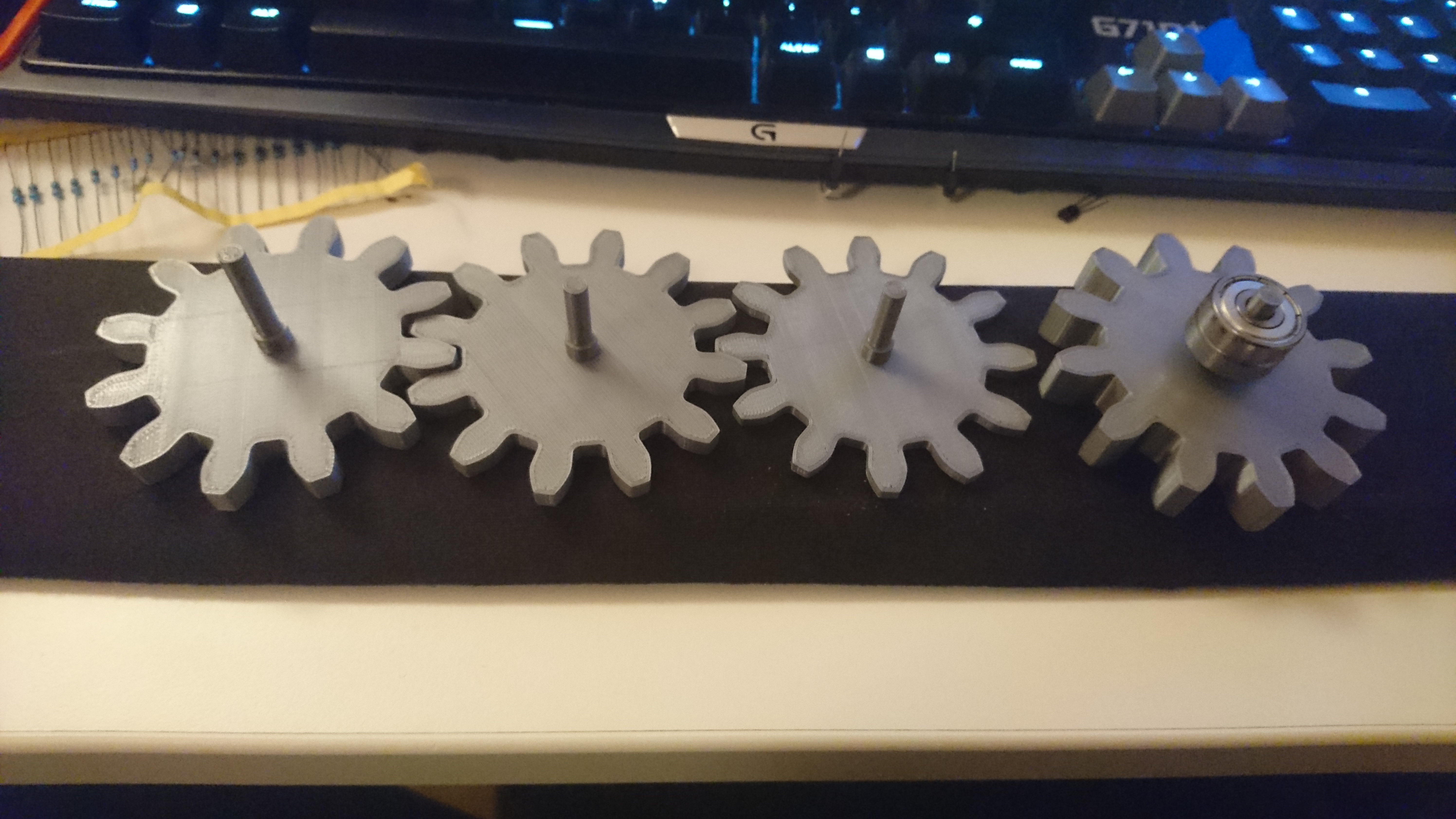
Then I realized the biggest mistake: the fit in the ball bearing was way too loose, to keep it in place enough. After printing out a lot of samples of new gears and the axis part, I finally got a good fit which was really tight. It turned out that I had to choose a wider diameter of the axis than the measured size of the ball bearing. I’m guessing that this is due to the shrinkage occuring when the PLA cools down combined with the small cylindrical shape of the axis.
I also extended the axis enough so I could fit a second Ball Bearing below the mount of the first one. And I planned to hotglue it to keep it in place.
And my second Revision of the table worked out great. Since I created the body in 3 parts, I only had to print the Table part again, which saved me a lot of time and material.
While the table printed, I went on and started to solder the components on the perf boards with mounts to keep it still fairly modular.
The main things I soldered were: resistors for the 7 segment so I could directly drive it off the Arduino pins.
After soldering, I started to figure out the pins of the display for the Arduino code, but made a big mistake… I forgot to use a resistor while testing and ended up blowing out the decimal point of the display I had.
No problem, I just go and get more of them. Or so I thought.
After getting replacement for the display (+ 4 spares) I tested the pins correctly and finished the code. Now I tested if the code actually displayed the numbers correctly, aaaaaaand… Nope. I was really confused since I couldn’t figure out the patterns at first.
At some point I again tested the 7 segment display by itself, and realised my problem: Instead of a configuration of all pins corresponding to an LED being + and the two additional pins being ground, these display actually functionend the other way around. Meaning, that the two additional pins take input current and you have to ground the pins you want to light up.
This made me angry, since I didn’t see why you would need the wiring this way around and I thought that I couldn’t use the circuit I already soldered.
Fortunately, after some research (and great help from a friend) I realized that I could just pull the arduino pins to HIGH to eliminate power flow and setting them to LOW when they should let power flow through. Testing this confirmed that I just had to slightly alter where and how I plugged in the breadboard cables in between the Interface perf board and the arduino one.
I already completed the arduino code at this point and went into the tweaking phase, where I slightly altered the variables of speed and distance to make more sense for the use case.
FINALLY COMPLETE – after a lot of time sunken into this project, I finally got a working product out of it. And since I built it from ground up it was a great feeling having it actually work.