Reinforcement Learning with Sim2Real on the Turtlebot3 platform (experiments)

While creating the concept of a new University module that has the students do a project with the Turtlebot3 robots and RL, a few ideas emerged. While evaluating different robot simulation tools for Reinforcement Learning, one in particular caught my eye: the Godot plugin “godot_rl_agents” by edbeeching. This was the result of a paper creating a bridge from Godot to RL libraries like StableBaselines3.

After trying the plugin it was clear that good result can be achieved quickly, there emerged the idea that students might be more encouraged learning the whole software stack when it involves a popular game engine instead of a “random” simulator with its own proprietary structure and configuration. So now it had to be proven that Sim2Real works with this Situation.

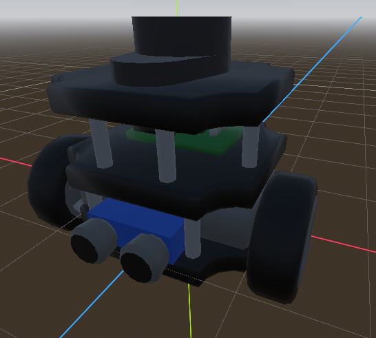
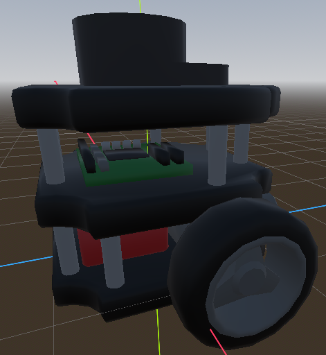
A friend modelled a “digital twin” of a turtlebot3, as the existing open source models usually used were very unoptimized and would hinder performance of actual training. It was purposefully minimal, but with accents to make it recognizable.

At first there was an example with just driving to a target point based on the map. No sensors needed.
Simulation:

This was the first result:

The robot visible moves pretty badly in this clip. The reason which was later found: When the sent velocity commands would result in a jerky movement, the controller kind of rejects it and sometimes only does a part of the movement. Or sometimes no movement at all. To counteract this, the input has to be smoothed out beforehand to resist rejection from the controller.

Here is the next experiment with the lerp in mind:

This was the result:

The video shows that the robots performance can definitely be improved regarding stability and sensor calculations. Another big problem is also very visible here in that the small metal caster on the back of the turtlebot is very incompatible with the labs’ carpet flooring. This will be mitigated in the future with wooden plates that will make up the box’s floor.

Bachelor Thesis: Non Destructive Reverse Engineering of PCBs

Full title of the thesis: Non Destructive Reverse Engineering of Printed Circuit Boards using
Micro Computed Tomography and Computer Vision

This post only aims to illustrate the main contents of the bachelor thesis, for the full overview, the original paper is best read in it’s full form.

Here is the abstract of the thesis:
Reverse engineering (RE) of printed circuit boards (PCBs) is used for a variety of purposes, such as in computer forensics and quality assurance. Usually RE is very labor-intensive or destructive, since it pertains either manually measuring all visible contacts, including desoldering the components for the covered pads and mapping them out individually, or the process is done by milling away layer by layer to see inside the object and uncover the traces. This thesis aims to automate the process as much as possible while being non-destructive. To achieve this, micro computed tomography (µ-CT) will be used to scan the PCB while information will be extracted with the help of computer vision.


The thesis researches the possibilities of using x-ray to reverse engineer PCBs. This makes it possible to understand PCBs without the need of damaging them using different methods.

The program was not finished at the end of the thesis, since the reconstruction part was still missing, but the whole procedure was shown to work in theory. Here are a few pictures taken from the thesis to visualize the problems:

Left to right: CT scan, pre-processed CT scan, edge detection visualized, original picture

This is a comparison of the fix by tilting the PCBs when scanning in a certain way:

This picture shows the edge detection up close and explains the coloured lines:

The picture below shows the algorithm recognizing two traces on the PCB

Note analyser

As a university project for the module “Multimedia”, I was in a team to develop hardware which would recognize single notes or cords being played on an instrument (tuned to piano sounds).

The project was run on a Raspberry Pi, and used the Fast Fourier Transformation to get the information needed. For a full writeup you best checkout the GitHub repository and the Printables entry.