While creating the concept of a new University module that has the students do a project with the Turtlebot3 robots and RL, a few ideas emerged. While evaluating different robot simulation tools for Reinforcement Learning, one in particular caught my eye: the Godot plugin “godot_rl_agents” by edbeeching. This was the result of a paper creating a bridge from Godot to RL libraries like StableBaselines3.
After trying the plugin it was clear that good result can be achieved quickly, there emerged the idea that students might be more encouraged learning the whole software stack when it involves a popular game engine instead of a “random” simulator with its own proprietary structure and configuration. So now it had to be proven that Sim2Real works with this Situation.
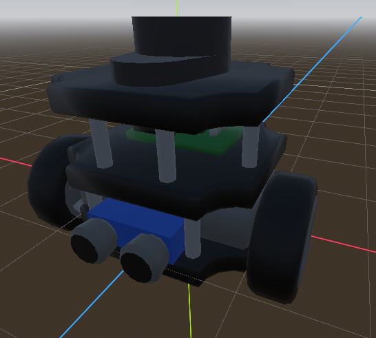
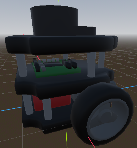
A friend modelled a “digital twin” of a turtlebot3, as the existing open source models usually used were very unoptimized and would hinder performance of actual training. It was purposefully minimal, but with accents to make it recognizable.
At first there was an example with just driving to a target point based on the map. No sensors needed. Simulation:
This was the first result:
The robot visible moves pretty badly in this clip. The reason which was later found: When the sent velocity commands would result in a jerky movement, the controller kind of rejects it and sometimes only does a part of the movement. Or sometimes no movement at all. To counteract this, the input has to be smoothed out beforehand to resist rejection from the controller.
Here is the next experiment with the lerp in mind:
This was the result:
The video shows that the robots performance can definitely be improved regarding stability and sensor calculations. Another big problem is also very visible here in that the small metal caster on the back of the turtlebot is very incompatible with the labs’ carpet flooring. This will be mitigated in the future with wooden plates that will make up the box’s floor.
The university I was a student at has a bunch of Turtlebot3 for student projects. And they got upgraded with a Jetson nano instead of the stock Raspberry Pi it had originally. After one student project on the new platform, it was clear that the Jetson nanos were good for calculating AI stuff, but terrible for reliability. So there was a plan to bring back the Raspberry Pis, but also keep the Jetson Nanos.
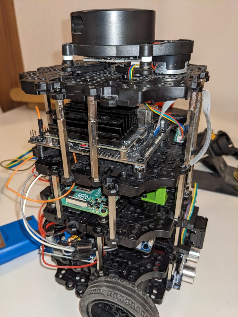
This was the initial rebuild:
This setup now has: – two motors – the OpenCR Board 1.0 for motor and battery control – A Raspberry Pi 4 4gb as the Robot brain with Ubuntu 22.04 and ROS Humble – A Jetson Nano for AI and Image operations – Various sensors (ultrasonic, button, fisheye camera, 2d lidar, imu)
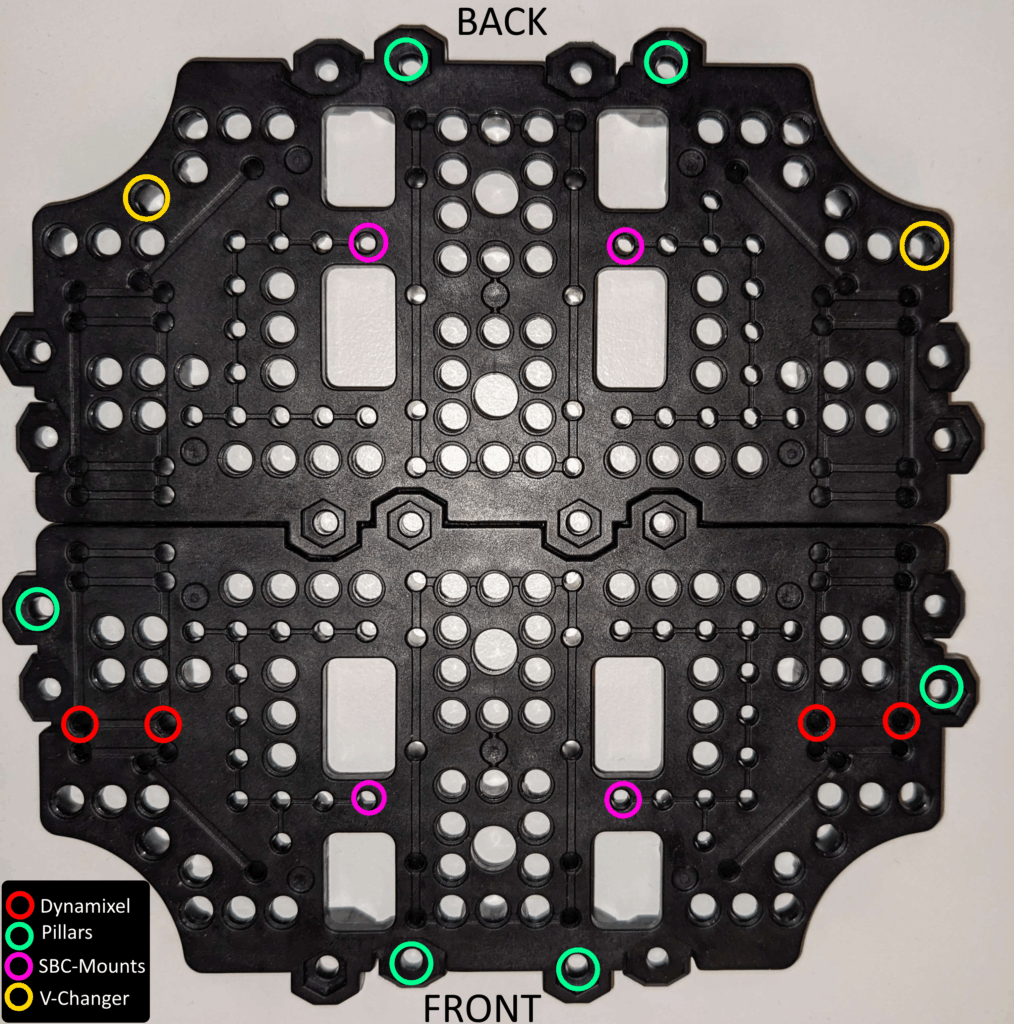
This prototype later got specific instructions what to screw in where, and short enough cables so they could be managed inside the robot. Another caveat that later popped up was that the power cables for the jetson nano were too thin, so a brown out occurred on power spikes. This was remedied by using the original barrel jack cables cut open and soldered in the place of the cables.
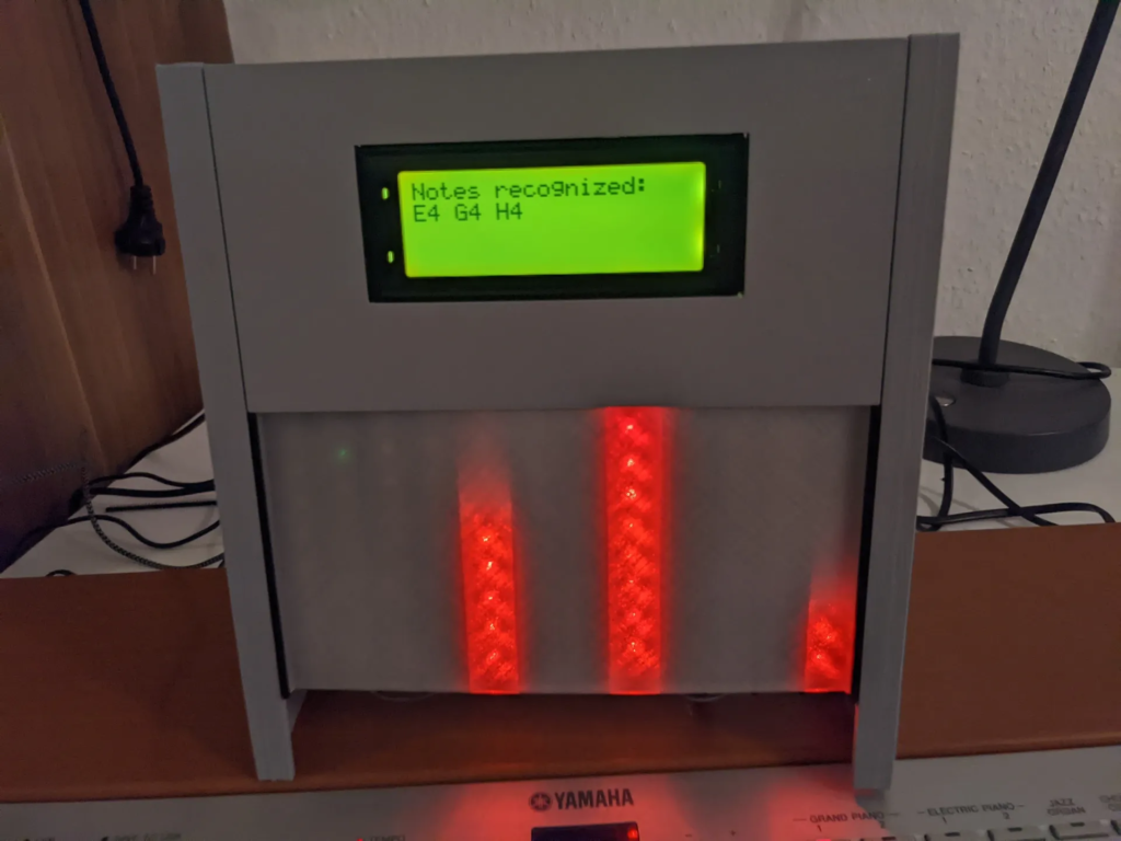
As a university project for the module “Multimedia”, I was in a team to develop hardware which would recognize single notes or cords being played on an instrument (tuned to piano sounds).
The project was run on a Raspberry Pi, and used the Fast Fourier Transformation to get the information needed. For a full writeup you best checkout the GitHub repository and the Printables entry.
With the want to create a more professional NAS solution than the one in my apprenticeship (just a raspberry pi with two external USB 1TB HDDs lying on the floor), I wanted to create something cheap, but still good and with good capacity.
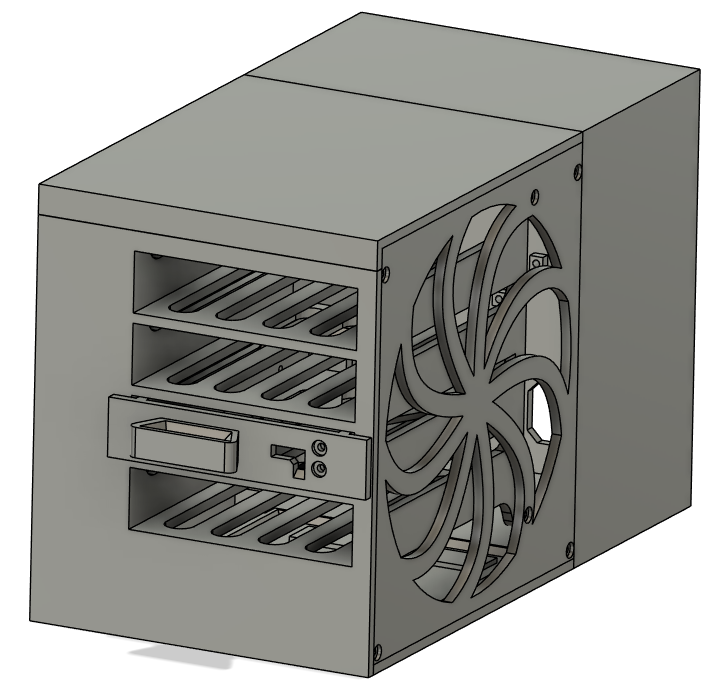
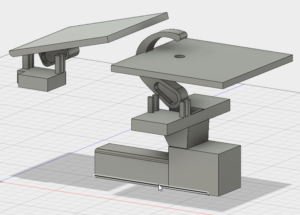
Since ready made NAS Enclosures would work, but are really expensive, I decided to Design my own in Fusion 360.
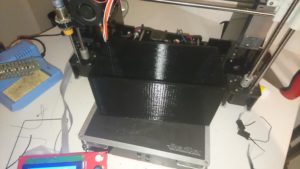
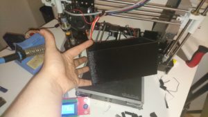
After finishing the model and printing it, I filled it with 4 2TB HDDs, which I configured in Raid 10.
In the back I placed the Raspberry Pi 4 and connected a daughterboard to control the Fans, as well as connecting the external ethernet port to enable a fast wired connection to outside the case. I also added a status LED, as well as a simple push button in order to have a “soft shutdown” button, which initiates a software shutdown. You can also just cut power with the power switch, but the soft shutdown is safer.
I’ve experimented with 3D scanning for some time now, and I thought that a turntable would help tremendously. Previous tries often had my hand interfering with the scans and it was difficult doing a “live scanning” with the kinect.
So I decided to build an arduino powered turntable that would have different modes and maybe even the ability to sync with my PC in some sense. Later on I decided to just focus on timed auto program with different levels of speed.
The idea of the internals came up fairly quickly, and I settled on: a cheap Stepper motor from my arduino set, an arduino nano (enough number of pins and a smaller footprint in size than an arduino uno), a digital encoder for input (acting as a dial, and the press to switch modes), a button as an additional input to switch the dial between modes and a 7 segment display with decimal point to display information.
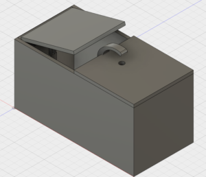
I started out with modelling the actual table part of the assembly. This was also my first time using the Gear script in Fusion 360. After playing around with the parameters of the script I completed the table part. Next up was the middle part to hold the motor and gears. For this I found the spec sheet of the stepper motor and used the dimensions to create the cutout. To keep it modular and easily accessible also made two differently sized holes to the bottom to slot into, and made the stepper motor slot with screw holes instead of a snap fit.
I started out the bottom with the cylindrical part and the notches. After this, I estimated the needed size of the interface and used join/cut operations to put the cube interface to the cylinder body.
The only thing left now was the face plate to keep the look clean. Since I decided to glue/weld it, it was fairly easy and quick to design.
After everything out, I had some real problems getting the motor to turn consistently. It got stuck very often and I had a hard time finding out why exactly that was. My first thought was the friction of the (not so smooth) 3D printed surfaces, but lowering friction with foil or tape proved difficult, since those seemed to catch on the rough surface even more.
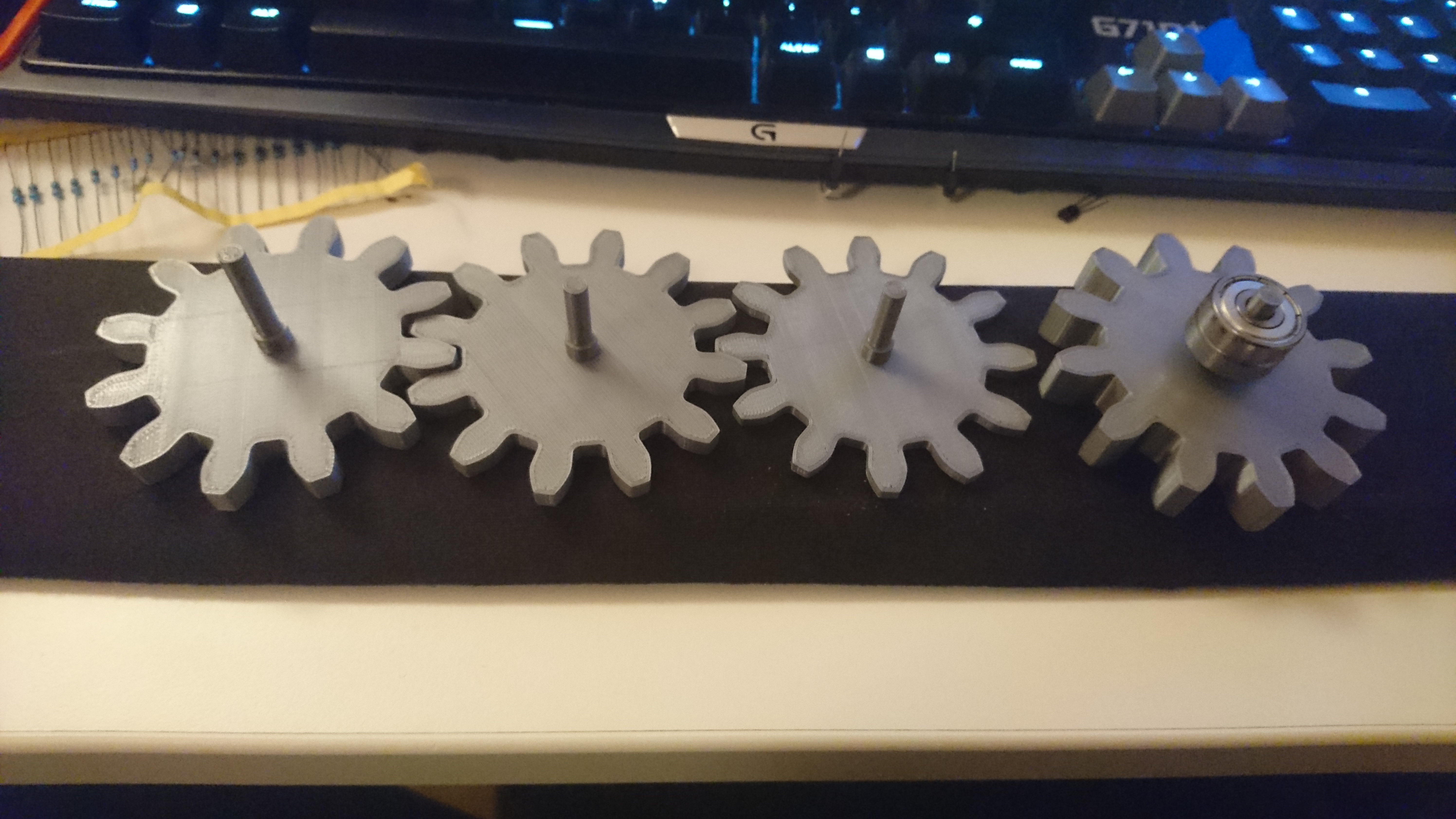
Then I realized the biggest mistake: the fit in the ball bearing was way too loose, to keep it in place enough. After printing out a lot of samples of new gears and the axis part, I finally got a good fit which was really tight. It turned out that I had to choose a wider diameter of the axis than the measured size of the ball bearing. I’m guessing that this is due to the shrinkage occuring when the PLA cools down combined with the small cylindrical shape of the axis.
Prototyping the perfect diameter of the axis
I also extended the axis enough so I could fit a second Ball Bearing below the mount of the first one. And I planned to hotglue it to keep it in place.
And my second Revision of the table worked out great. Since I created the body in 3 parts, I only had to print the Table part again, which saved me a lot of time and material.
While the table printed, I went on and started to solder the components on the perf boards with mounts to keep it still fairly modular. The main things I soldered were: resistors for the 7 segment so I could directly drive it off the Arduino pins.
After soldering, I started to figure out the pins of the display for the Arduino code, but made a big mistake… I forgot to use a resistor while testing and ended up blowing out the decimal point of the display I had. No problem, I just go and get more of them. Or so I thought.
After getting replacement for the display (+ 4 spares) I tested the pins correctly and finished the code. Now I tested if the code actually displayed the numbers correctly, aaaaaaand… Nope. I was really confused since I couldn’t figure out the patterns at first. At some point I again tested the 7 segment display by itself, and realised my problem: Instead of a configuration of all pins corresponding to an LED being + and the two additional pins being ground, these display actually functionend the other way around. Meaning, that the two additional pins take input current and you have to ground the pins you want to light up.
This made me angry, since I didn’t see why you would need the wiring this way around and I thought that I couldn’t use the circuit I already soldered. Fortunately, after some research (and great help from a friend) I realized that I could just pull the arduino pins to HIGH to eliminate power flow and setting them to LOW when they should let power flow through. Testing this confirmed that I just had to slightly alter where and how I plugged in the breadboard cables in between the Interface perf board and the arduino one.
I already completed the arduino code at this point and went into the tweaking phase, where I slightly altered the variables of speed and distance to make more sense for the use case.
FINALLY COMPLETE – after a lot of time sunken into this project, I finally got a working product out of it. And since I built it from ground up it was a great feeling having it actually work.
I have bought a used Kinect V2 (the Xbox One version) and converted it for PC usage. This eliminates the need of an overly expensive kinect-to-USB adapter cable. The kinect itself uses a modified version of a USB B 3.0 plug. The only modification is that it also carries the 12V required to run the sensors.
And you can actually feed the 12V through the extra pin directly and use a normal USB B 3.0 cable for your PC to connect. I won’t go over the process in Detail, but it is quite easy to do anyway:
Step 1 Open the Kinect up (you need to peel off some glued on stickers that cover the screws on the bottom)
Step 2 Solder a power cable to the respective Pin and Ground.
Step 3 Close it back up.
After this you just need a 12V 3A power supply and connect that to the soldered on connection. The rest is a thing of installing the kinect sdk on the PC for it to recognize the kinect correctly.
For this I followed several tutorials to make sure I make the correct steps.
When trying to think of a nice birthday present for a friend I came up with one of these “useless machines” we both love the thought of.
So my final plan was: have a more complex, arduino controlled useless machine that is still programmable and runs of an easily removable USB power bank. This way the this becomes a 2-in-1 gift: the power bank and the actual mechanism.
My initial plan was to build two of these things – one as a prototype and a second cleaner, better version as the actual gift. So I ordered the parts I’d need twice and started designing in Fusion 360.
At first I wanted to make on 100% myself and just used those of other people as a reference. Well, that didn’t really work out, since after printing it out I realized it A: didn’t work and B: was way too big.
This is what my first version looked like. After starting to print it out I ditched that and revised my plan. Here is the body printed out:
So from then on I decided that I’d take an existing model and modifiy it to my needs. I ended up using this model from thingiverse: https://www.thingiverse.com/thing:1258082
I remodeled the bottom plate of the box to suit my need and create a “hotplug” functionality with the power bank.
After assembling my first prototype of the top half and coding a basic switch function this happenend:
Sooooo I had to slightly adjust the code for it to work.
After putting together the a behaviour of the box I was happy with I printed a second batch of Parts and assembled it. The second version got a lot cleaner than the first one. I also glued in a little stretchable string to hold down the lid.
In the code I not only had a few “animations” it could randomly choose, but also a few idle “animations” when the switch doesn’t get pressed for some time.
For a while I have kinda struggled with humidity in my apartment. Opening windows doesn’t do much and gets uncomfortable after a while when it’s really hot or cold outside.
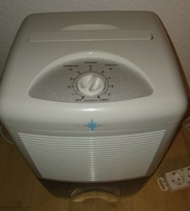
So I purchased a dehumidifier some time ago. It worked great so far, but it just didn’t behave like I wanted it to.
So I thought I’d make a small project out of it to see where I can push it. After opening it up, I quickly realized that the control circuitry is buried deep inside the device, and since it quite expensive I decided against opening it up further. So instead of directly interfacing with it, I had to get creative.
The dial on the top was also plastered with rivets, and I didn’t want to do anything irreversible.
So I went for my only idea I had left – even though it felt a little bit awkward: letting a servo turn the dial and leave the rest of the device alone.
For that I quickly whipped up a 3D model of a little clip for the servo to grab onto the dial, and of course a holder to have the servo stay in the required position. After a bit of measuring I based the holder design on the clip I used to upgrade cardbot. The first version fell a bit short, so I had to adjust the length of the pillars and print it again.
I used 3M glue pads to hold the holder in place.
I needed to tweak the code several times, as well as fix a huge oversight I had at the start, which just made the arduino switch the positions after each time out.
I’m really happy with how this turned out though. Maybe I’ll replace the two potentiometers with static resistors in the future, so I can use them for other projects.
While teaching a friend of mine about the arduino set I recommended to him, he had an idea for a little project he wants to try next. I thought the thought was interesting, so I gave it a try myself so I can help him more easily.
The task: Have the arduino generate random numbers to use for the “LOTTO 6 aus 49” lottery. The numbers to generate are simple: you need 6 numbers from 1 to 49 and one “Superzahl” from 1 to 9 at the end. The Numbers should be displayed on the LCD display so you can easily run it on battery and make it portable.
My solution: To my current knowledge none of the available random functions are truly random. Especially on the Arduino they’re Pseudo-Random and not quite the solution we’re looking for. Even though it would be random enough in theory, I wanted to try and find a more unpredictable way. My idea to do that was to introduce the human factor. Making it similar to a slot machine, I used a button that the user would have to press for each number while the Arduino loops through all the possibilities one by one on each tick. Once the button is pressed it locks the number in and starts the loop for the next one.
I think this way is the closest to “truly random” as you can get easily with just these components.
I will include a download link to the source code below, but it still has one obvious flaw: it doesn’t check for duplicates – which is not possible to use for the actual lottery. I decided that I were done with this contraption, since my friend had the duplication check figured out fairly quick on his own.
While being active in the community of Letsrobot I got an offer to try a product of Bare Conductive in trade with a documented project I do for their own blog. I got really interested in the product, so I agreed. It did take me a few months to actually finish it, but I have finally completed the project and got featured on both bare conductive’s site as well as adafruit’s one.
The product in question is the “Pi Cap” which is a hat for the Raspberry pi and adds a bunch of Capacitive touch and distance sensors. I wanted to make a product with my robots I built with LetsRobot in mind. Often enough I had people ask me to toss a ball across the room so they could fetch it, kinda like a pet. That’s what gave me the idea of a automatic fetch machine – like the ones that shoot tennis balls for dogs so they can play with themselves.
I ran into quite a few problems along the way. To list the biggest ones:
Detection of the ball/robot: I thought I could make the capacitive sensors pick up the robot and motors, but that didn’t work at all. Also I needed the ball to be picked up somehow and didn’t needed a way to make that work as well.
Creating the 3D models: While I already got some experience with smaller and less complicated models and thought I could create such models with some work. It took way longer than I thought, but eventually I managed to finish them.
Below a small gallery of the different steps I completed.
A summary of how it works: The script in the background is written in python and runs on the raspberry in the background. The Pi Cap senses the ball with a cable to a little aluminum foil piece which touches the ball when inserted into the loading arm. The arm is designed in such a way that the ball always rolls in the right spot to make contact. Once it senses something the script pauses for a few seconds to give the robot time to get out of the way. After that it sends a new positon for the loading servo to the servo microcontroller. This causes the ball to roll into the shooting head. After spinning up the two DC motors placed to accelerate the ball, the script moves the second servo to push the ball into the two motors. I also integrated a small LED to indicate the script sensing the ball and doing stuff.